Finnley (Active Guidance on Medium-Powered Rocket)
System Modules
Finnley: Active Canard-Controlled Model Rocket

Project Overview
Finnley represents an ambitious exploration into active rocket stabilization through a custom-designed, medium-power rocket featuring actuating canards for flight control. Developed in 2021 over approximately two months, this project pushed beyond traditional passive fin stabilization to implement a fully integrated control system capable of nulling angular acceleration during flight. The entire vehicle was designed and built from scratch, incorporating 3D-printed structural components, a hand-soldered flight computer, and a novel dual-canard control mechanism.
Technical Challenge and Approach
The project was born from a long-standing ambition to build an actively stabilized rocket. Rather than pursuing the more common approaches of thrust vector control (TVC) or aft-fin actuation—both notoriously difficult to implement—the canard configuration offered a compelling middle ground. Mounted forward on the airframe, the canards could generate control authority while remaining mechanically simpler than gimbaled engine mounts or complex fin actuator systems.
The control architecture centered around a PID (Proportional-Integral-Derivative) controller with the specific objective of nulling angular acceleration. This meant the system would actively counteract any rotational motion detected by onboard sensors, maintaining stable flight orientation throughout the powered ascent and coast phases.
Flight Computer Design (FC2)
At the heart of Finnley's control system was FC2, a completely custom flight computer hand-soldered on perfboard. This decision to build rather than buy reflected both a desire for deep system understanding and the need for precise integration with the canard actuation mechanism.

The flight computer incorporated an Adafruit Feather M0 microcontroller as its computational core, interfaced with a comprehensive sensor suite including a 3-axis accelerometer, gyroscope, and barometric pressure sensor. These sensors provided the real-time state estimation necessary for closed-loop control. Power came from a single-cell lithium polymer battery, with a custom power distribution circuit managing the dual servo motors that drove the canards.
Beyond core control functionality, FC2 featured both an OLED display and NeoPixel LED for state indication and data output—critical for ground testing and pre-flight verification. A LoRa radio module enabled wireless communication, allowing both telemetry downlink during flight and remote command uplink for test sequences.
Innovative Wind Tunnel Validation
Perhaps the most technically impressive aspect of the Finnley project was the custom wind tunnel testing apparatus developed to validate the control system before committing to actual flight. This test rig consisted of a rectangular duct housing an 11-inch propeller driven by a drone motor, creating sufficient airflow to simulate flight conditions. The rocket's control module was suspended within this airstream using fishing line, allowing completely free rotation while experiencing aerodynamic forces.
The test methodology demonstrated sophisticated systems integration. With the wind tunnel motor running, commands were transmitted wirelessly via LoRa from a laptop to the rocket's flight computer, initiating automated test sequences. These sequences would first deliberately spin up the vehicle to a target rotation rate using the canards, then demonstrate active stabilization by controlling back to rest—all while maintaining airflow. The success of these tests provided concrete validation that the PID controller, sensor fusion, and servo actuation could work together to achieve the desired control objective.
Looking back from 2025, this wind tunnel validation remains one of the project's standout achievements, representing a level of ground testing sophistication unusual for amateur rocketry.
Design Complexity and Integration Challenges
The two-month timeline belied significant design complexity, particularly in the CAD phase. Every component had to be carefully positioned to accommodate cable routing between the flight computer, servos, sensors, and battery while maintaining serviceability for pre-flight checks and post-flight analysis. The 3D-printed payload section required multiple design iterations to achieve the necessary structural integrity while minimizing weight—a constant tension in rocket design.

The canard actuation mechanism employed a gear reduction system, with each servo driving a pinion gear that meshed with a larger gear mounted directly on the canard pivot. This arrangement provided both increased control precision and higher torque output, essential for overcoming aerodynamic loads during flight.
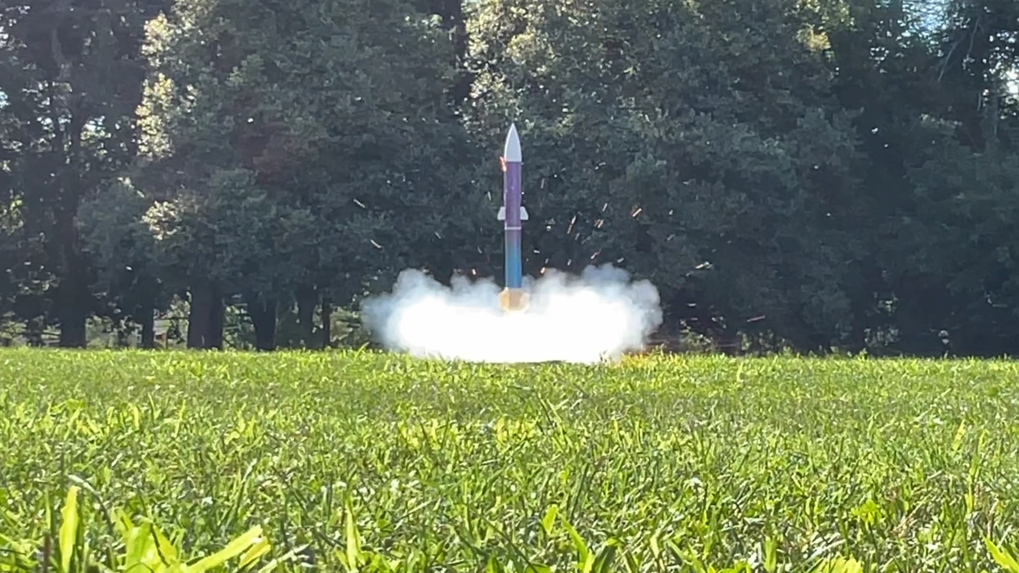
Flight Test and Lessons Learned

Finnley's single flight test revealed both the promise and pitfalls of the design. The rocket successfully launched and entered its active control phase, with radio telemetry confirming that the flight computer had transitioned to closed-loop stabilization mode. However, a critical structural failure emerged in the canard gearing system.
The failure mechanism was subtle but instructive: while one canard was mounted such that aerodynamic forces pushed its gear into tighter mesh with the servo pinion, the opposite canard experienced forces that worked to separate the gears. Under flight loads, this second canard's gears slipped, eliminating control authority on one side and preventing proper stabilization.
Compounding the challenge of post-flight analysis, the primary telemetry data failed to record to the SD card due to an undetermined issue, leaving only the partial radio telemetry captured during flight. This highlighted the importance of redundant data logging systems in experimental vehicles.
Legacy and Impact
Despite the flight ending in partial failure, Finnley represented a successful proof-of-concept for canard-based active stabilization and demonstrated the viability of entirely scratch-built control systems. The lessons learned—particularly regarding mechanical design under aerodynamic loading and the criticality of telemetry redundancy—have informed subsequent projects. The wind tunnel testing methodology alone stands as a reusable validation approach applicable to future control system development, and the experience gained in sensor fusion, real-time control, and electromechanical integration continues to resonate in current work.